Published: Nov 24, 2023 by Yihao Liu
Difference between hFSM and the hFSM proposed in the paper “Toward Process Controlled Medical Robotic System”
If you are not interested in some stories, go straight to the last 4 paragraphs, that’s the real stuff of this long blog.
In the first few of my PhD group meetings in 2021, a very respected (I mean very respected) professor was quite nervous about our ways of directly using a collaborative robot (Kuka iiwa, they have a medical version now) to place something to people’s head. I started my PhD with projects focusing on robotic Transcranial Magnetic Stimulation, which does exactly that.
Truth to be told, not long after I realized the systems built by PhD students and the code base in those systems, with the primary goal to do research but not to start an FDA vetted, multimillion dollar medical device company, can sometimes be pretty flimsy. Even though most of us try our best to build maintainable and trustable systems, sometimes they may end up being just slightly better than a toy. I mean, you get it. Prototyping a proof-of-concept is very different from building a commercialized product with a bunch of highly paid product managers and engineers.
I started to think about how to make it absolutely safe even in the prototyping of a research project.
An image guided robotic system is usually very large and complex. In the prototyping of a research project, different components are not always connected seamlessly. You will see some PhD students perform experiments awkwardly because they need to calibrate the robot, plan some targets in the navigation system, start medical image registration, command the robot to go there, and repeat. Many of the time, these are not done in the same computer workspace. If any of the steps was messed up, you need to start over. This created some space for risky moves. So, I thought, can we put these steps together and make the pipeline to be controlled.
The first thing came to mind is an FSM. That seems easy. I just need to attach a changing mode to the controller. Well, as we all know, everything you thought would be easy, will go against your expectation and bite you so hard. I drew a bunch of diagrams trying to model only 4 different states. They really didn’t look pretty. The programming was in C++ so it made the thing even worse. Long story short, I was able to simplify it a little, and in the end, you see this figure from my PCMRS paper.
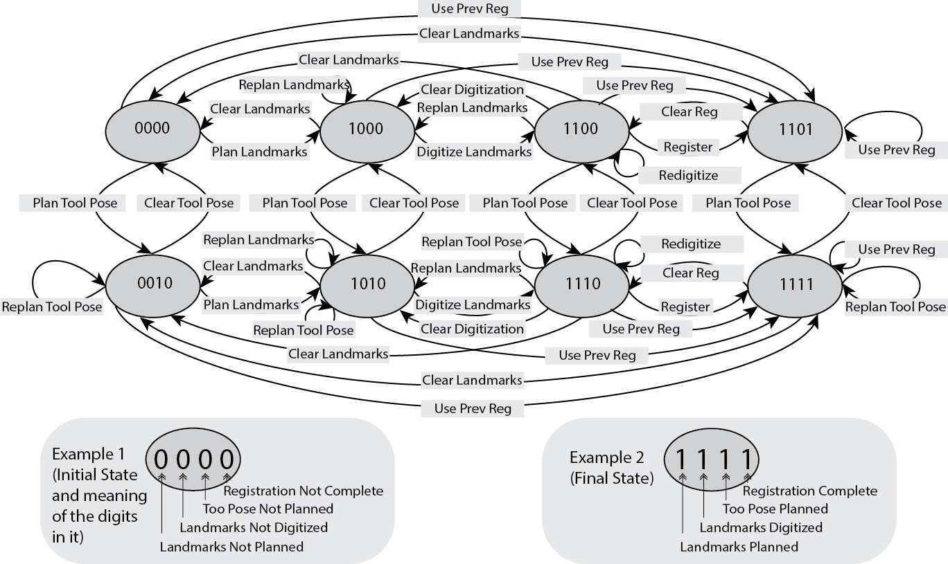 Figure 1.
How I did it was this: I use a digit, 0 or 1, to represent if a procedure has been done or not. It is essentially a flag (which I really dislike if it is not in the context of FSM. I actually talked about this in the PCMRS paper). Then, if you had a pipeline that has 5 steps, then you get 5 pairs of 0/1’s. Now you combine the states of all steps into one single string: 00000, 00001, 00010, and so on. That becomes your state in the FSM. That was obviously not simplified enough. Can I simplify it more? You will realize, some of the steps are dependent to each other. Say, step 3 can only happen if step 2 has been done. Then, 00100 is not valid, because it translates to “step 1 not finished, step 2 not finished, step 3 finished, step 4 not finished, step 5 not finished”. You can really trim down a bunch of the states.
Can I do better?
I thought some of the steps really can be done in parallel, is it worth it to put them in the same state string? Maybe not. How about I separate those and make them smaller pieces. (It was funny to mention that on that day of the year of 2021, I thought I discovered something groundbreaking. Little did I know: ) Someone in 1984 already did it. And he named it Hierarchical Graph Schemes.
You can also call it Hierarchical Finite State Machine (hFSM), a method to divide a complex state machine formulation of a system into manageable pieces. Applying this to the original figure, I got this. That was so much better.
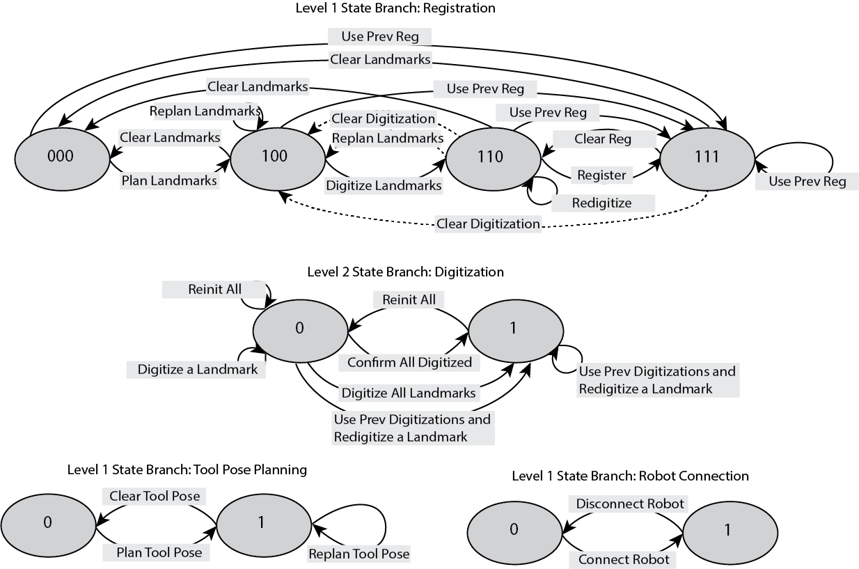 Figure 2.
From this setup, I came up some pretty interesting future directions that was hinted in the PCMRS paper. I will probably cover them in some more blogs once they are out of my self-imposed secrecy stage. I have been thinking about the setup since last year when I finished the coding for my own system. With some more inspection, I had discovered some subtle differences of the OG hFSM and the hFSM in the PCMRS paper.
The major two differences are the dependency between micro- and macro- states, and the meaning of a “state”.
Firstly, the dependency between micro- and macro- states. Say you modeled some states like in this Figure 3. It has the transitions between State1, State2, and State3, and the micro-transitions between State2.1, State2.2, and State2.3. Note in the figure I connected OperationA, C, D to State2.1, which may not be the same in other people’s work. Some work will only connect the operations to State2 (like in Figure 4, which I got from the Internet), not those micro-states. In that case, it implies transitions of State2.x are independent of State1 and State3. This is not always the case. In Figure 2 again, you can observe the micro-states (I defined them to be states in a state branch of level “N+1” in the paper) to be dependent on macro-states (“N” level state branch). For example, I wrote this in the caption of the Figure 2: “The registration state branch has a level 2 branch (digitization) at 100 to 110. Any incoming operation to 100 with no direct lower state transition (dash lines) should call the reinitialization state of the digitization branch. Any level 2 state change (from one state to another) must emit a signal to the corresponding level 1 state”. This is the reason I tried to formulate the Rule1-3 in the paper, even though they are in my opinion, after a year or so, not the most elegant solution and there is space to improve, but that is another day’s work.
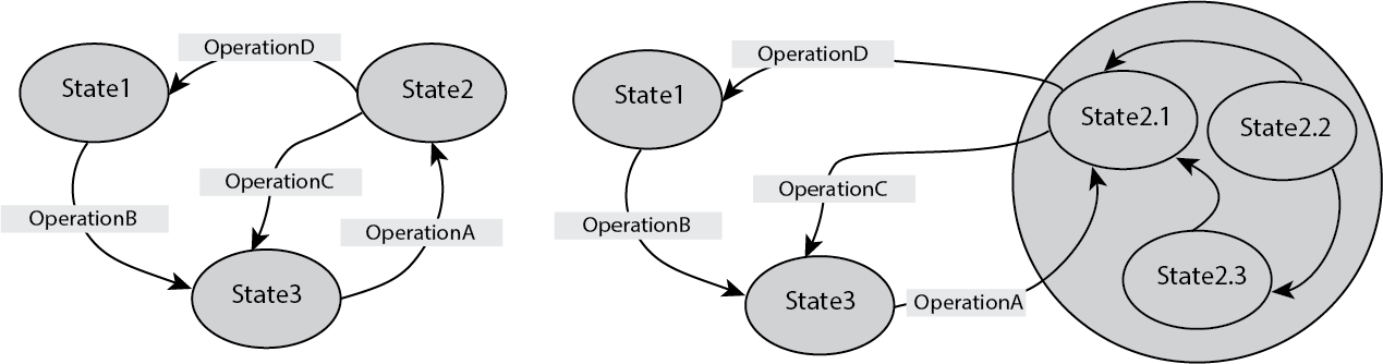 Figure 3.
Secondly, the meaning of a “state”. This is more or less a design choice. If you look up online you will see some tutorials about modeling the states in examples such as “running”, “jumping”, and “static”. Using hFSM you get “moving” to include both “running” and “jumping”. In my case, I wanted a result-oriented design. I care more about whether a step is finished or not, while you can still add processing like running and jumping in the bigger model. Thus, I chose to have those “state digits” like 01110 or 10001. This way, each state essentially means multiple results – a combination of the facts in the world. I found it very useful in my case.
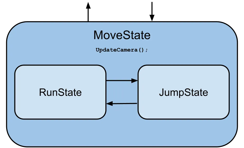 Figure 4.
Now you will understand that Figure 2 should separate the “state branches”. Merging the “state branches” into one single diagram like Figure 3 might be harder than expected, because each macro-state (registration) contains a description of the micro-state (digitization). In other words, regular hFSM can have a state to be another FSM, while the hFSM in PCMRS, can have a “state digit (a digit in the 10001 string) to be another FSM”. You need to cram the corresponding states in level “N+1” to each corresponding state digit in level “N”. It is still theoretically doable, but separating them is probably the easiest. The pitfall is to handle the Direct Incoming Operation (DIO) and Indirect Incoming Operation (IIO) well, as defined in the paper.
In conclusion, FSM is certainly not a new concept, but you can play with it to tailor to your need. I am still trying to make some improvements to the system described in the PCMRS paper and in this blog. It is the infrastructure of some more interesting stuff I will cover later, so please stay tuned.